Mining & Aggregate · Crusher Drive Gear Technology
Rock crushers — jaw, cone, gyratory, and impact types — process millions of tonnes of ore and aggregate annually, demanding drive systems that deliver massive sustained torque while surviving the relentless shock loads from crushing hard rock. Planetary gearboxes serve as the primary or secondary speed reducer in crusher drive trains, providing the torque density and impact resistance these brutal applications require. This article covers the engineering and maintenance of planetary gearboxes for mining and aggregate crusher drive systems.
Crusher Drive Train Architecture
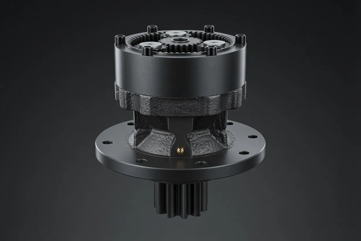
A typical crusher drive train consists of an electric motor (200 to 2,000 kW), a coupling or clutch, and one or two reduction stages that convert motor speed (typically 1,000–1,500 RPM) to the crusher’s operating speed (200–600 RPM for cone crushers, 100–300 RPM for gyratory crushers). A planetary gear reducer serves as the primary reducer in compact drive configurations or as a secondary reducer in combination with a V-belt or gear-motor primary stage. The planetary arrangement’s high torque density allows the reducer to fit within the tight space between the motor and the crusher mainframe, often in locations where a conventional parallel-shaft gearbox would be too large to install.
Crusher gearboxes must transmit torque that fluctuates dramatically as rock enters and passes through the crushing chamber. Each piece of rock that enters the chamber creates a load spike as it fractures, followed by a brief unloading as the fragments fall through the discharge gap. On a large cone crusher processing hard granite, these load cycles occur dozens of times per second, creating a high-frequency torque oscillation superimposed on the steady-state crushing load. The high torque planetary gearbox must handle this complex loading spectrum without fatigue failure of the gear teeth or rapid deterioration of the bearings.
Load Conditions in Crusher Applications
Continuous Heavy-Duty Operation
Production crushers operate 18 to 24 hours per day, accumulating 6,000+ operating hours per year. The gearbox runs under full torque for the vast majority of this time, with brief unloaded intervals only during maintenance stops and feed interruptions. This sustained loading demands gears and bearings with fatigue lives calculated for continuous duty — not the intermittent duty ratings that suffice for many industrial applications. The planetary gear reducer must deliver its full rated torque at thermal equilibrium, meaning the heat generated by gear mesh and bearing friction is fully dissipated through the housing without progressive temperature rise.
Shock and Tramp Metal Events
When non-crushable objects — tramp metal, drill bits, or extremely hard rock — enter the crushing chamber, the resulting torque spike can reach 300–500% of the steady-state crushing torque. These events are unpredictable and can occur at any time during operation. The gearbox must survive thousands of such events over its service life without cumulative gear tooth damage. Overrunning clutches or shear-pin couplings upstream of the gearbox provide a degree of protection, but the gearbox itself must have sufficient overload capacity (typically 300% of rated torque) to handle the events that pass through the protective device.
High-Vibration Environment
Crushers generate intense vibration from the rock-crushing process, and this vibration propagates through the frame to the gearbox mounting. The gearbox housing and internal components must resist fatigue under this continuous vibration loading. Bolted housing joints must be designed with adequate clamping force and locking provisions (Nordlock washers, thread adhesive) to prevent loosening under vibration. Bearing fits must be tight enough to prevent fretting between the bearing outer ring and housing bore, a common failure mode in high-vibration applications that can be difficult to distinguish from normal bearing fatigue.
Design Specifications for Crusher Gearboxes
⚙️ Service Factor Sizing
Crusher gearbox service factors range from 1.5 for uniform-feed crushers (well-screened feed, no tramp metal) to 2.5 for primary crushers processing run-of-mine ore with frequent tramp metal events. Applying the appropriate service factor to the motor’s rated torque determines the required gearbox catalog rating.
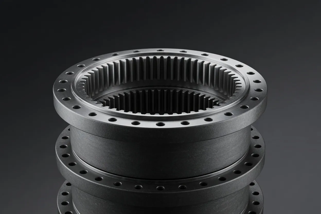
Shock-Resistant Gear Metallurgy
Through-hardened alloy steel gears (AISI 4340 or equivalent) with core hardness of 28–34 HRC provide the toughness needed to absorb impact loads without brittle fracture. For the most severe applications, case-carburized gears with carefully controlled case depth (balancing surface hardness against core ductility) offer the best combination of wear resistance and impact toughness.
️ Heavy-Duty Bearings
Spherical roller bearings with enhanced cage designs handle the combined radial loads, misalignment, and vibration characteristic of crusher installations. Bearing life calculations must include the dynamic factor for shock loading (typically 1.5–2.0 for crusher duty) to ensure the L10 life exceeds the planned overhaul interval.
Thermal Capacity
Continuous full-load operation requires the gearbox to reach thermal equilibrium at an oil temperature below the lubricant’s rated limit (typically 90–100 °C for synthetic EP oils). The housing’s surface area, material (cast iron conducts heat better than steel fabrication), and the availability of external cooling determine the thermal capacity.
Installation and Alignment
Foundation Design
Mount the gearbox on a rigid concrete or structural steel foundation that is independent of the crusher’s vibration path. Isolating the gearbox foundation from the crusher foundation prevents transmitted vibration from accelerating gearbox bearing and gear wear. Where shared foundations are unavoidable, install vibration-damping pads between the gearbox feet and the foundation.
Shaft Alignment
Align the motor-gearbox and gearbox-crusher shaft connections to within 0.05 mm parallel and angular offset. Crusher vibration constantly challenges alignment, so install flexible disc or gear couplings that tolerate minor dynamic misalignment without transmitting damaging radial loads to the gearbox bearings. Recheck alignment after the first 500 operating hours and correct any drift.
Oil System Commissioning
Fill the gearbox with the specified oil grade, connect external cooling lines (if equipped), and run the unit at no-load for 30 minutes to circulate oil through all bearings and gear meshes. Verify oil flow through any external cooler circuits and confirm that the oil temperature stabilizes below 60 °C under no-load conditions.
Vibration Baseline
Capture a comprehensive vibration spectrum at the gearbox housing during the first week of operation under normal crushing load. This baseline spectrum identifies the normal gear mesh and bearing frequencies and their amplitudes, providing the reference point for all future condition monitoring comparisons.
Maintenance and Planetary Gearbox Maintenance Best Practices
Crusher gearbox maintenance follows a condition-based approach, using oil analysis and vibration monitoring to schedule interventions. Monthly oil sampling tracks wear-metal trends and lubricant condition. Quarterly vibration surveys detect developing gear and bearing faults. An integrated approach — combining both data sources — provides the most reliable prediction of remaining useful life. When either oil analysis or vibration data indicates an approaching limit, schedule a gearbox inspection or exchange during the next planned crusher maintenance shutdown.
Oil changes at 4,000-hour intervals (or sooner based on analysis) maintain the lubricant’s protective properties. Use the same oil brand and viscosity grade throughout the gearbox’s life — mixing oil brands risks additive incompatibility that can destabilize the lubricant film and accelerate wear. During each oil change, inspect the magnetic drain plug and any inline filters for metallic debris quantity and particle size distribution. Large particles (above 500 μm) indicate active gear tooth damage; fine particles (below 100 μm) are normal wear. A sudden increase in fine particle concentration often precedes a detectable vibration change by several weeks, providing an earlier warning that maintenance planning can exploit.
Why Choose Ever-Power for Crusher Planetary Gearboxes
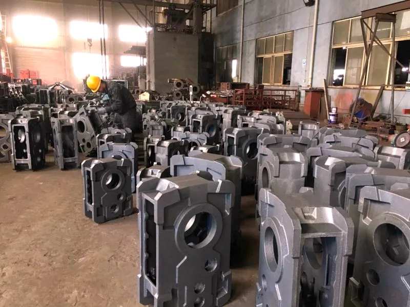
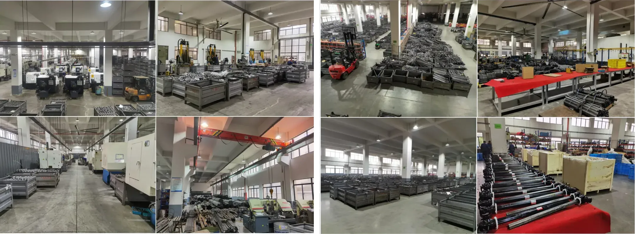
Mining-Duty Manufacturing Standards
Our crusher gearboxes are manufactured from premium alloy steels with full metallurgical certification, heat treatment to controlled specifications, and 100% non-destructive testing of critical components — the quality standard expected by mining operators and aggregate producers worldwide.
Shock-Load Validation
Every crusher gearbox model undergoes 10,000 shock-load cycles at 300% of rated torque on our test stand, verifying that the design can survive the tramp-metal events and hard-rock impacts characteristic of crusher duty without measurable damage.
️
Crusher OEM Partnerships
We supply planetary gearboxes to crusher manufacturers across Asia, Africa, and South America, with application engineering support that matches gearbox specifications to each crusher model’s specific load profile and installation geometry.
Mining Site Delivery
We coordinate heavy-freight logistics to remote mining sites, including customs documentation, special transport permits for oversized crates, and site-delivery scheduling aligned with plant shutdown windows. Contact [email protected] for site-specific logistics planning.
Frequently Asked Questions
Keep Your Crusher Running at Full Throughput
Share your crusher model and operating parameters — our mining equipment team will deliver a gearbox proposal engineered for your specific duty cycle.