Foundation Engineering · Rotary Drilling Rig Drives
Rotary drilling rigs bore large-diameter shafts into the earth for building foundations, bridge piers, and retaining walls. The rotary drive head — the rig’s primary working mechanism — uses a planetary gearbox to convert hydraulic motor torque into the slow, massive rotational force needed to turn drilling tools through soil, rock, and concrete. This guide covers the engineering requirements, selection criteria, and maintenance practices for planetary gearboxes in rotary drilling rig applications.
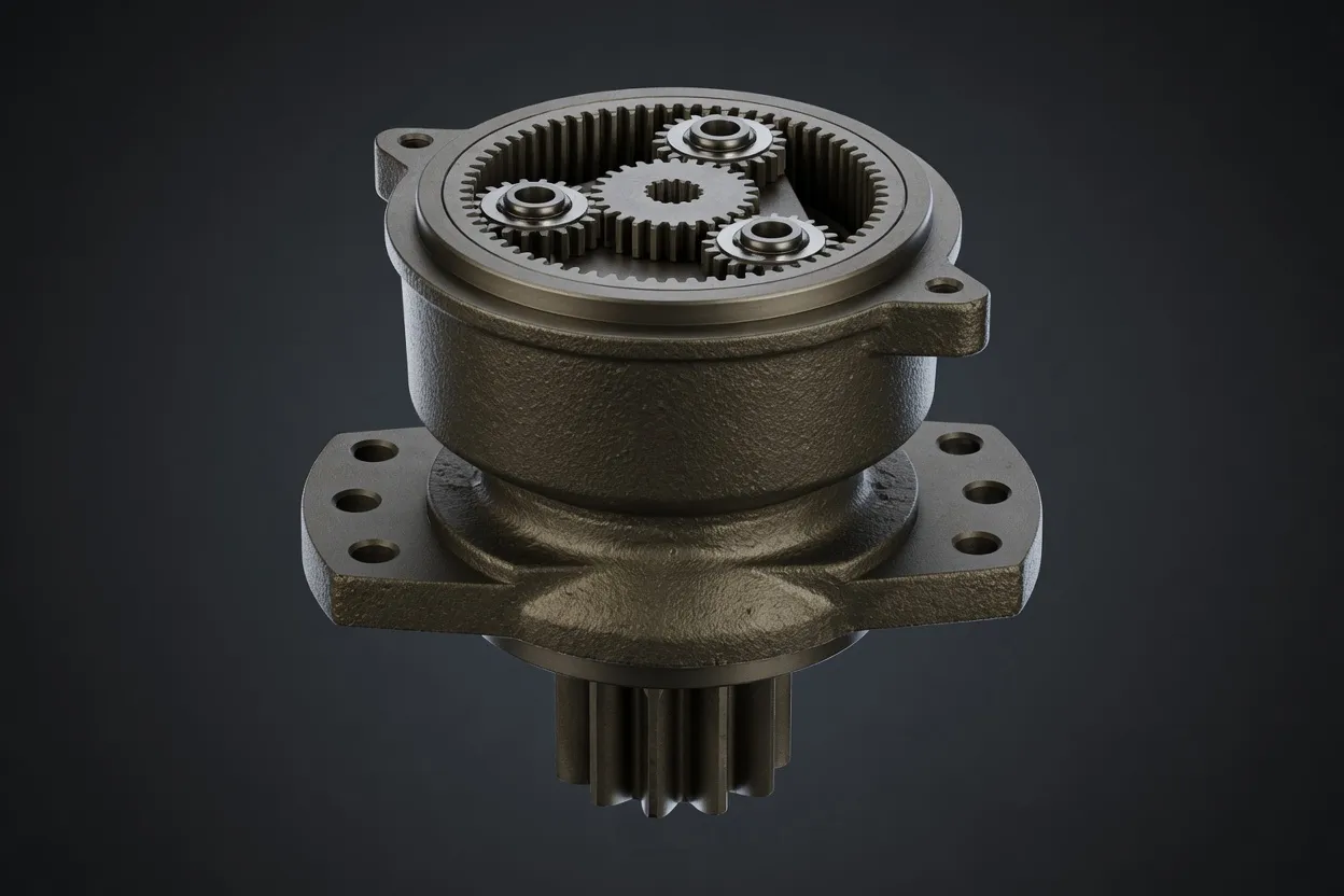
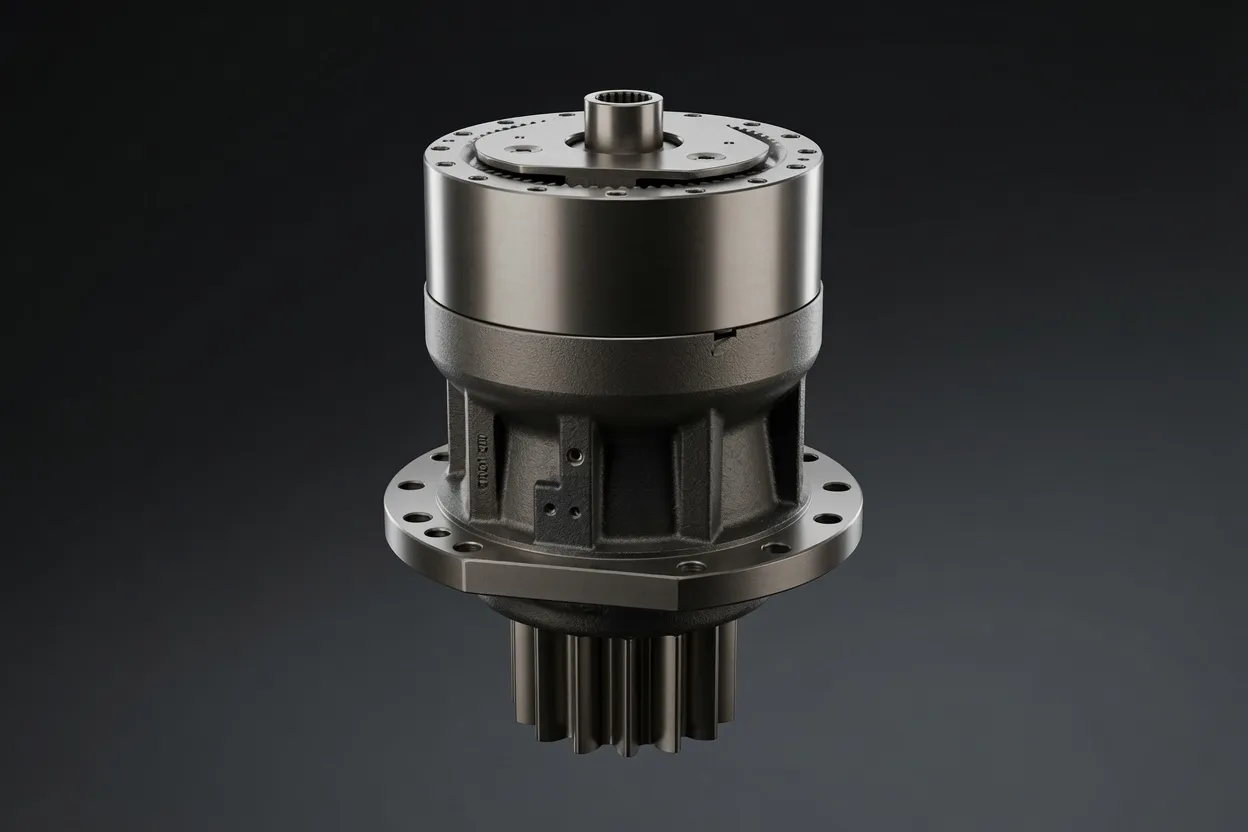
Rotary Drive Head Architecture
The rotary drive head sits atop the drilling rig’s Kelly bar or continuous-flight auger, transmitting rotational torque and vertical crowd force into the drilling tool. One or two hydraulic motors power a multi-stage planetary gear reducer with overall ratios of 20:1 to 60:1, delivering output torques from 50 kNm on small foundation rigs to 500+ kNm on large-diameter bored-pile machines. The drive head travels vertically on the rig’s mast, feeding the drilling tool into the ground while rotating it at speeds of 5 to 30 RPM depending on the soil conditions and tool type.
The gearbox must transmit torque bidirectionally — clockwise for drilling and counterclockwise for reaming or tool extraction — and must handle the torque fluctuations that occur as the drilling tool encounters varying ground conditions within a single bore. A layer of soft clay may transition suddenly to dense gravel or cobbles, generating torque spikes that can reach 200% of the average drilling torque. The high torque planetary gearbox must absorb these transients without gear damage while maintaining smooth, controllable rotation at the output.
Torque and Speed Requirements by Ground Condition
Soft Soil Drilling
In clay, silt, and loose sand, the drilling tool encounters relatively low rotational resistance but requires high output speed (15–30 RPM) to maximize drilling productivity. The gearbox operates at moderate torque — 30 to 50% of its rated capacity — with the primary demand being sustained efficiency at elevated output speeds. Low-ratio single-stage or two-stage planetary reducers suit these conditions, providing the speed range needed for rapid bore advancement while holding sufficient torque margin for occasional harder layers.
Hard Rock and Concrete
Drilling through weathered rock, boulders, or existing concrete foundations demands the gearbox’s full rated torque at low output speed (5–10 RPM). The drilling tool grinds and fractures the material progressively, generating sustained high-torque loading with superimposed vibration from the cutting process. Three-stage planetary gearboxes with ratios above 40:1 provide the torque multiplication and shock absorption needed for these severe conditions. Gear teeth must resist the cyclic stress from vibration-induced torque oscillation without developing fatigue cracks at the tooth root.
Mixed Ground Conditions
Urban foundation drilling frequently encounters alternating layers of fill, natural soil, and rock — sometimes within the same bore. The rig operator adjusts motor speed and gearbox output in real time to match the changing resistance. The planetary gear reducer must perform well across its entire speed-torque envelope, from high-speed light-load operation in soft ground to low-speed maximum-torque operation in rock, without overheating, excessive noise, or efficiency degradation at either extreme.
Design Features for Drilling Rig Gearboxes
⚙️ Overload Capacity
Drilling gearboxes are rated with a service factor of 2.0 or higher — meaning the gearbox’s catalog torque rating is at least twice the average drilling torque. This margin accommodates the torque spikes from hitting buried obstructions, the torsional oscillation from rock cutting, and the reverse-torque events during tool extraction.
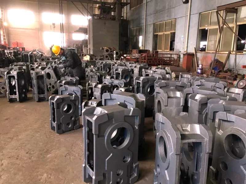
High-Stiffness Housing
The gearbox housing must resist the combined drilling torque and vertical crowd force without deflecting enough to misalign the internal gears. Ductile iron (GGG50) or fabricated steel housings with thick walls and reinforcing ribs provide the structural stiffness needed. FEA analysis validates that housing deflection under maximum combined loading keeps gear mesh alignment within the tolerance needed for full-face tooth contact.
️ Contamination Protection
Drilling rigs operate in dusty, muddy environments, and the drive head may be partially submerged in drilling fluid (bentonite slurry) during wet boring operations. IP66 sealing and pressurized breather systems prevent the ingress of drilling fluid and abrasive soil particles that would contaminate the gear oil and accelerate internal wear.
️ Oil Cooling Provision
Sustained high-torque drilling generates substantial heat in the gear meshes and bearings. Large-frame drilling gearboxes incorporate oil-cooling circuits — either integral heat-exchange fins on the housing or connections for an external oil cooler supplied by the rig manufacturer. Maintaining oil temperature below 80 °C preserves lubricant performance and extends bearing fatigue life.
Integration with the Drilling Rig
Motor Interface
The hydraulic motor bolts directly to the gearbox input flange, with the motor shaft splined into the gearbox input sun gear. Verify spline engagement length and alignment before tightening the mounting bolts. Insufficient engagement causes spline wear that manifests as torsional play — mimicking gearbox backlash — within the first few hundred operating hours.
Kelly Bar or Auger Connection
The gearbox output drives the Kelly bar through a drive table or directly engages the continuous-flight auger’s hexagonal drive shaft. The connection must transmit the full rated torque without slip and must also accommodate the vertical travel of the Kelly bar or auger during drilling advancement. Wear pads or replaceable drive bushings at this interface protect the gearbox output from the abrasive wear caused by drilling-fluid-contaminated soil particles.
Crowd Force Load Path
The vertical crowd force — pushing the drilling tool downward into the ground — passes through the drive head gearbox housing to the mast via the drive head’s slide carriage. Verify that the gearbox mounting to the carriage is rigid enough to prevent rocking under combined torque and crowd loading, which would cause cyclic housing deflection and accelerated bearing wear.
Commissioning and Baseline Testing
After installation, run the drive head at full speed under no-load conditions and record motor pressure, gearbox housing temperature, and vibration levels. These baseline values serve as the reference for future condition monitoring. Repeat the measurement under full-load drilling conditions to verify that all parameters remain within acceptable limits.
Maintenance and Condition Monitoring
Drilling rig planetary gearboxes operate in demanding conditions that shorten maintenance intervals compared to stationary industrial equipment. Change the gear oil every 1,000 operating hours or sooner if oil analysis indicates contamination. Check the oil level daily before starting drilling operations — a low level indicates a seal leak that must be corrected before operating. Inspect the magnetic drain plug at each oil change for metallic debris, and submit an oil sample for laboratory wear-metal and particle-count analysis quarterly.
Vibration monitoring provides the most reliable early warning of developing gear or bearing problems. Mount a triaxial accelerometer on the gearbox housing and capture a vibration spectrum monthly during standard drilling conditions. Trend the amplitudes at gear-mesh frequency and bearing characteristic frequencies — a 6 dB increase from baseline warrants investigation, and a 10 dB increase warrants scheduling a gearbox exchange at the next rig move. This approach prevents in-bore failures that would require emergency crane mobilization to extract the drilling tool — an extremely costly and time-consuming recovery operation.
Why Choose Ever-Power for Drilling Rig Gearboxes
Foundation Equipment Expertise
Our drilling rig gearbox range covers rotary drive heads from 50 kNm to 500 kNm output torque, compatible with major rig brands including Bauer, Liebherr, Casagrande, Soilmec, and XCMG. Each model is validated for the torque spikes and mixed-ground conditions typical of urban foundation work.
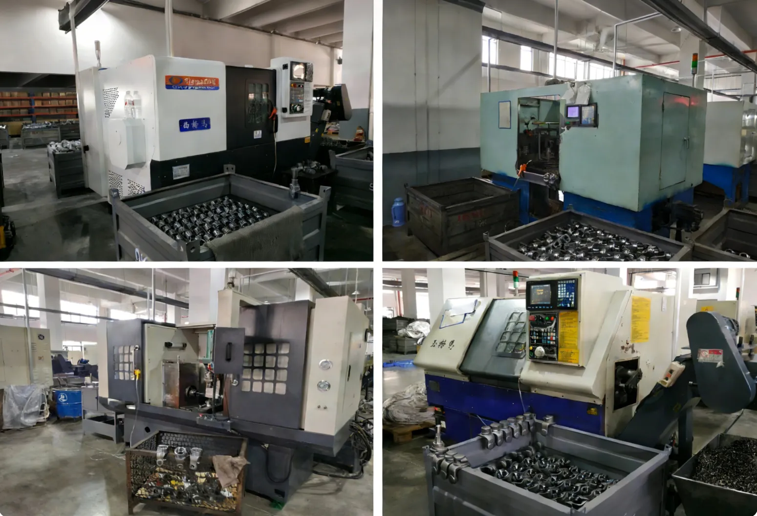
Extended Overload Testing
We test every drilling gearbox model at 200% of rated torque for 500 hours in our laboratory, simulating the severe overload events that occur during hard-rock drilling. Only designs that complete this test without measurable damage enter our product catalog.
️
Rapid Field Exchange
We maintain exchange-stock units for popular rig models, shipping within 5 business days. A rig that loses a drive head in mid-project can receive a replacement unit quickly, minimizing project delay and crane idle costs. The removed unit returns to our factory for rebuild and restocking.
Project-Based Supply
Foundation contractors working on large-scale projects receive project-dedicated pricing, scheduled deliveries, and technical support throughout the project duration. Contact [email protected] to discuss project supply arrangements.
Frequently Asked Questions
Power Your Drilling Rig with Confidence
Share your rig model and project soil conditions — our engineering team will recommend the optimal drive head gearbox.