Wind Energy · Main Drive Gearbox Technology
The main gearbox of a utility-scale wind turbine converts the rotor’s slow, high-torque rotation — typically 8 to 15 RPM — into the 1,500 or 1,800 RPM required by the generator. This speed multiplication factor of 100:1 or more, combined with power ratings of 2 to 8 MW passing through a single gear train, makes the wind turbine main gearbox one of the most demanding planetary gear applications in industrial engineering. This article covers the architecture, material requirements, lubrication strategies, and reliability challenges of planetary gearboxes in wind turbine main drive systems.
Architecture of a Wind Turbine Main Gearbox
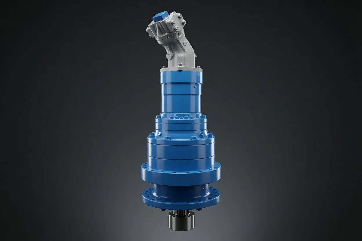
Modern wind turbine gearboxes use a combination of planetary and parallel-shaft helical stages to achieve the required overall speed-up ratio within the nacelle’s space and weight constraints. A typical configuration for a 3 MW turbine uses one or two planetary stages at the low-speed (rotor) end, where torques reach 2,000 to 4,000 kNm, followed by one or two parallel-shaft helical stages at the high-speed (generator) end. The wind turbine planetary gearbox stages carry the heaviest loads and dominate the gearbox’s size and weight, while the parallel-shaft stages handle the faster, lower-torque portion of the speed multiplication.
The planetary stage’s load-sharing geometry is essential at these power levels. Three to five planet gears mesh simultaneously with the sun and ring gears, distributing the massive rotor torque across multiple contact points rather than concentrating it on a single gear pair. This allows the gearbox to transmit multi-megawatt power within a housing that fits inside the nacelle — a cylindrical structure only 4 to 6 meters in diameter. Without the torque-density advantage of the planetary arrangement, the gearbox would need to be impractically large and heavy for tower-top installation, where every additional kilogram increases structural loads on the tower and foundation.
Load Conditions Unique to Wind Turbine Gearboxes
Turbulent and Transient Torque Profiles
Wind is inherently turbulent, generating torque fluctuations on the rotor that propagate through the gearbox at frequencies ranging from sub-hertz gusts to blade-passing frequencies of 0.5 to 1.5 Hz and their harmonics. These fluctuations superimpose on the steady-state torque, creating a dynamic load spectrum far more complex than the constant-speed, constant-load conditions that govern most industrial gearbox applications. The multi-stage planetary gearbox must be designed for fatigue under this variable-amplitude loading, using damage-accumulation methods (Palmgren-Miner rule) applied to measured or simulated load spectra spanning the turbine’s 20-year design life.
Non-Torque Loads from the Rotor
Wind turbine rotors generate not only torque but also thrust forces, bending moments, and yaw moments that transfer through the main shaft into the gearbox. These non-torque loads — reaching 500 kN of thrust and 3,000 kNm of bending moment on a 3 MW turbine — distort the gearbox housing and misalign the gear meshes if the support structure is insufficiently rigid. Modern gearbox designs use three-point or four-point suspension systems that isolate the gearbox from rotor bending moments, directing non-torque loads to the main frame through the main bearing rather than through the gearbox housing.
Emergency Stops and Grid Events
Emergency stops triggered by high wind speed, grid faults, or sensor anomalies impose severe transient torques on the gear train. The braking torque reverses the normal power flow direction, loading gear tooth flanks that may not be equally hardened or finished if the gearbox was designed primarily for unidirectional operation. Grid events — sudden generator load rejection or reconnection — create torsional oscillation within the drivetrain that excites the gear train’s natural frequencies. The high torque planetary gearbox must survive thousands of these events over the turbine’s service life without cumulative fatigue damage to the gear teeth or bearings.
Planetary Gear Design for Multi-Megawatt Wind Turbines
⚙️ Gear Material and Heat Treatment
Wind turbine planetary gears are forged from 18CrNiMo7-6 or equivalent high-grade case-carburizing steel, achieving a surface hardness of 58–62 HRC and a core hardness of 34–40 HRC. The deep case depth (2–4 mm) provides the wear-resistant surface needed for the high Hertzian contact stresses — exceeding 1,500 MPa — at the planet-ring and planet-sun meshes under peak loading conditions.
Tooth Flank Modification
Profile crowning, lead crowning, and tip relief modifications compensate for elastic deformation of the gear teeth, shafts, and housing under load. Without these modifications, edge loading at the tooth ends accelerates micropitting and scuffing. Loaded tooth contact analysis (LTCA) using FEA guides the modification parameters, which are verified by contact-pattern paint checks on assembled gearboxes before commissioning.
Planet Bearing Configuration
Each planet gear rotates on its own bearing set — typically cylindrical roller bearings or tapered roller bearings with integral thrust washers. These bearings must handle the radial loads from gear meshing plus the centrifugal loads from planet carrier rotation, with rated lives exceeding 150,000 hours (L10a) to meet the turbine’s 20-year design target without bearing replacement.
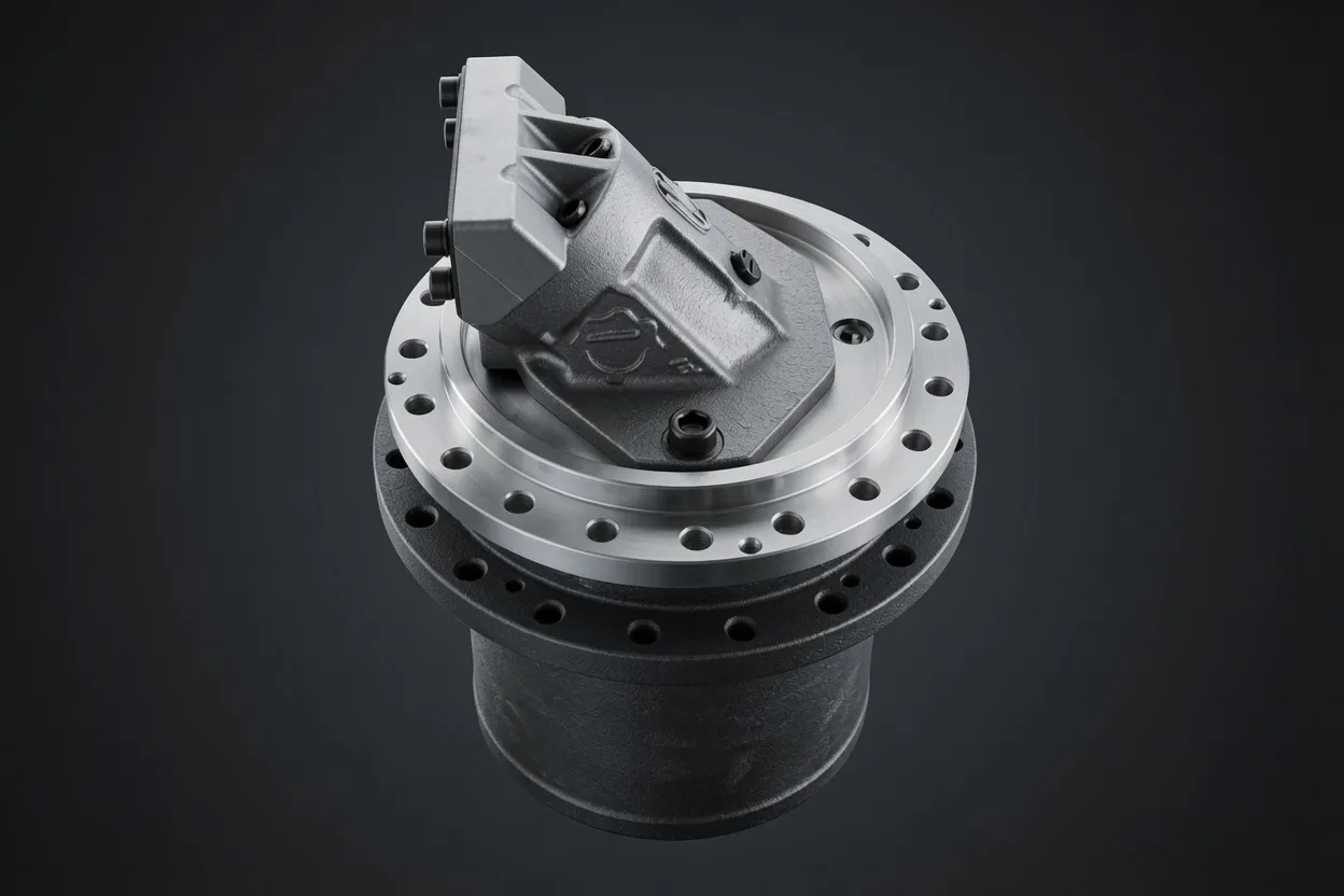
️ Ring Gear Integration
The ring gear may be integral with the gearbox housing (cast and machined from a single piece) or bolted in as a separate component. Integral designs reduce weight and eliminate the bolted joint as a potential failure point, while separate ring gears simplify field replacement if tooth damage occurs during the turbine’s service life. Both approaches require the ring gear bore to maintain cylindricity within 30 μm to ensure uniform planet-ring mesh engagement.
Lubrication and Cooling Systems
Wind turbine gearboxes use forced-circulation oil systems that continuously pump lubricant through the gearbox, supplying oil jets to each gear mesh and bearing. The oil simultaneously lubricates, cools, and flushes wear debris from the gear train. Typical oil volumes range from 300 to 800 liters for turbines in the 2–5 MW class, with flow rates of 100 to 300 liters per minute providing adequate cooling under rated-power conditions. External oil coolers — either air-cooled radiators or water-glycol heat exchangers — maintain oil temperature within the 50–70 °C operating window that balances viscosity for gear-tooth film thickness against low enough drag to limit churning losses.
Oil condition monitoring is a cornerstone of wind turbine gearbox reliability. Inline particle counters, water-content sensors, and oil-quality sensors provide continuous data to the turbine’s SCADA system, triggering alarms when contamination levels exceed thresholds. Annual laboratory oil analysis supplements online monitoring with spectroscopic wear-metal analysis and infrared testing for oxidation and additive depletion. Maintaining oil cleanliness to ISO 4406 16/14/11 or better and water content below 200 ppm are widely accepted targets for maximizing gear and bearing fatigue life in wind turbine service.

Reliability Challenges and Field Experience
Micropitting and White Etching Cracks
Micropitting — fine surface pitting caused by rolling-contact fatigue under boundary lubrication — is the most common gear damage mode in wind turbine gearboxes. It begins as a cosmetic surface change but can progress to material removal that alters the tooth profile and increases noise, vibration, and dynamic loading. White etching cracks (WEC) in bearings represent a more severe and less well-understood failure mode, where subsurface cracks form and propagate without the classic indicators of surface-initiated fatigue. Both phenomena are subjects of ongoing research, with current mitigation strategies including superfinished gear surfaces, optimized lubricant additives, and black-oxide bearing treatments.
Condition Monitoring and Predictive Maintenance
Remote condition monitoring systems — combining vibration analysis, oil particle counting, and temperature trending — enable wind farm operators to detect developing gearbox faults weeks or months before functional failure. This advance warning allows maintenance to be scheduled during low-wind periods, minimizing energy production losses. Vibration signatures at gear-mesh frequencies and bearing characteristic frequencies are the primary diagnostic indicators. Fleet-level analytics, correlating gearbox condition data with operational and environmental data across hundreds of turbines, further refine fault detection algorithms and enable remaining-useful-life prediction for individual gearboxes.
Why Choose Ever-Power for Wind Turbine Gearbox Components
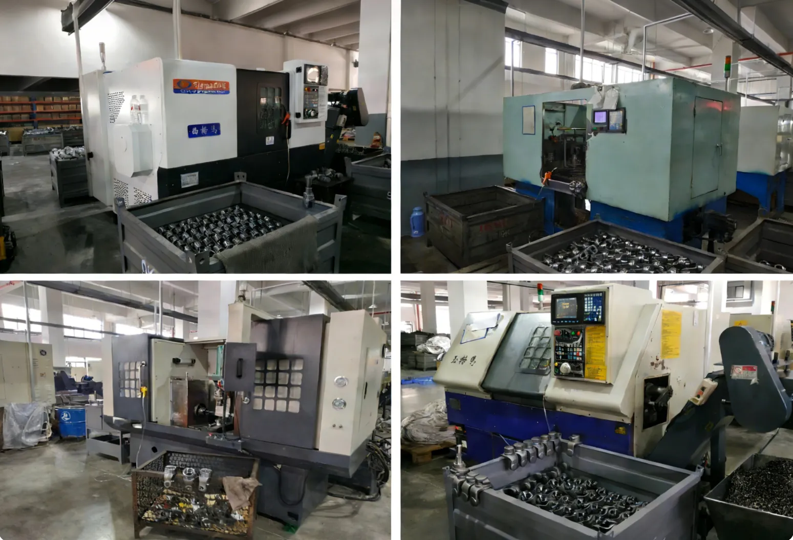
Heavy-Duty Gear Manufacturing
Our facility machines and grinds wind-turbine-class planetary gears up to 2,000 mm diameter, using CNC gear grinders with in-process quality measurement to achieve AGMA Class 11 or higher on every tooth — the accuracy standard required for MW-class wind gearboxes.
Material and Metallurgical Expertise
We maintain in-house metallurgical laboratory capabilities for case-depth profiling, hardness mapping, microstructure analysis, and residual-stress measurement. Every gear lot receives full metallurgical certification traceable to the raw material heat, providing the documentation that wind turbine OEMs require for component approval.
Wind farms needing replacement planetary gear sets for in-service gearboxes receive reverse-engineered, drop-in-compatible components with lead times that minimize turbine downtime. Provide the gearbox model and gear part number — we deliver replacement gears meeting or exceeding the original specification.
Global Wind Energy Logistics
Oversize planetary gears ship on custom-built crates designed for safe transport to remote wind farm locations. We coordinate heavy-lift logistics from our Hangzhou facility to ports, wind farms, and gearbox repair centers worldwide.
Frequently Asked Questions
Keep Your Wind Turbines Running at Full Power
Share your turbine model and gearbox component requirements — our wind energy team will deliver a technical proposal with lead time and pricing within 5 business days.