Wind Energy · Yaw Drive Planetary Gear Systems
The yaw system rotates the entire nacelle of a wind turbine to face the rotor into the prevailing wind direction, maximizing energy capture across changing wind conditions. Each yaw drive module — four to eight are installed per turbine — uses a planetary gearbox to multiply the electric motor’s torque into the massive rotational force needed to turn a nacelle weighing 50 to 200 tonnes against friction, gravity, and aerodynamic loads. This article covers the engineering demands, design criteria, and reliability practices for planetary gearboxes in wind turbine yaw drive applications.
Yaw System Architecture and Gearbox Function
A yaw system consists of a yaw bearing (a large slewing ring mounted between the nacelle and tower top), multiple yaw drive modules spaced around the bearing circumference, a yaw brake, and a control system that commands yaw movements based on wind direction data from the nacelle-mounted wind vane. Each yaw drive module houses an electric motor coupled to a planetary gear reducer with an overall ratio of 500:1 to 2,000:1. The gearbox output shaft carries a pinion gear that meshes with the internal or external ring gear of the yaw bearing, translating the motor’s rotary motion into nacelle rotation.
During normal operation, the yaw system makes small angular corrections — typically 2 to 5 degrees — every few minutes to track gradual wind direction changes. Under turbulent or gusty conditions, larger and more frequent adjustments are needed. The gearboxes must deliver sufficient torque to overcome the friction of the yaw bearing, the aerodynamic forces acting on the rotor, and any cable-twisting resistance from the power cables that descend through the tower. At the same time, they must be capable of holding the nacelle in position against the wind when the yaw brake is released during repositioning movements.
Torque Requirements and Load Cases
Normal Yaw Operation
During routine wind tracking, each yaw drive module contributes a share of the total yawing torque required to rotate the nacelle. For a 3 MW turbine with six yaw drives, the total yawing torque may reach 800 kNm under adverse conditions, requiring each module to deliver approximately 135 kNm at the pinion. The high torque planetary gearbox in each module must sustain this torque continuously during the yaw movement — which may last 30 to 60 seconds — without overheating. The intermittent duty cycle, with yaw movements followed by stationary holding periods, allows the gearbox to dissipate heat between movements.
Extreme Wind and Emergency Conditions
During storm events with wind speeds above 25 m/s, the turbine may need to yaw rapidly to maintain alignment or to reach a safe parking position. The yaw drive gearboxes must deliver 150–200% of their normal operating torque for short durations under these extreme conditions. Additionally, if one yaw drive module fails, the remaining modules must compensate for the lost torque contribution, operating at elevated individual loading until the turbine can be shut down for maintenance. The gearbox’s short-time overload capacity — rated for 200% of nominal torque for 30 seconds — provides this operational margin.
Static Holding and Yaw Brake Interaction
When the yaw brake is engaged, the brake pads clamp the yaw bearing to hold the nacelle against wind-induced yaw moments. However, the yaw drives must also resist any yaw loads that exceed the brake’s holding capacity during extreme gusts. The gearbox’s self-locking characteristics at high reduction ratios (above 500:1) provide an additional holding mechanism — the gear train’s internal friction prevents the wind-induced torque from back-driving the motor, even if the yaw brake momentarily slips under peak loads.
Gearbox Design Specifications for Yaw Drives
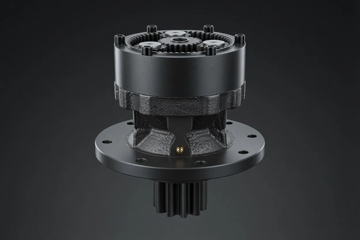
⚙️ Multi-Stage Reduction
Yaw drive ratios of 500:1 to 2,000:1 require three or four planetary stages in series. Each stage contributes a ratio of 4:1 to 8:1, and the compounded product of all stages yields the overall ratio. Careful distribution of the ratio across stages optimizes the load sharing — the first stage handles the highest torque at the lowest speed, requiring the largest gears and bearings.
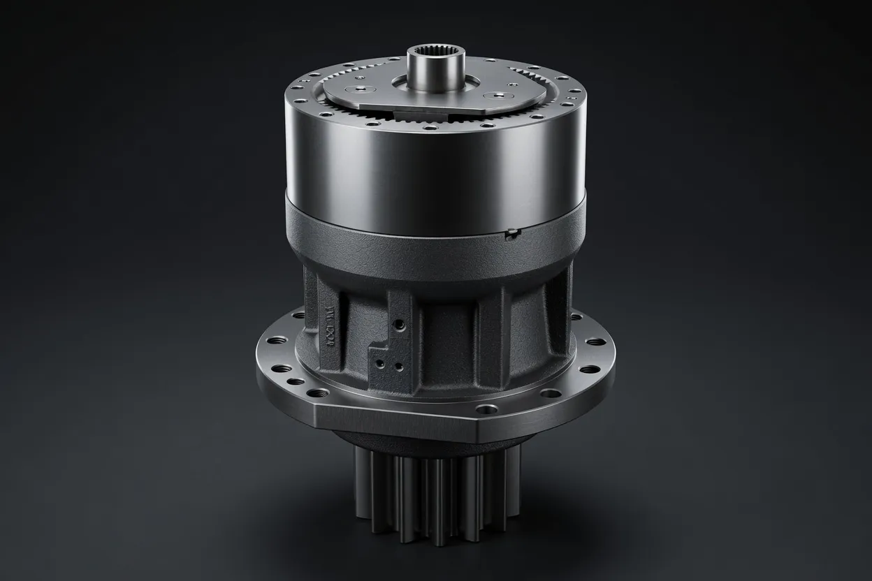
Output Pinion Integration
The gearbox output shaft typically terminates in a hardened steel pinion that meshes with the yaw bearing’s ring gear. The pinion must be case-carburized and ground to AGMA Class 10+ to withstand the high contact stresses at the bearing interface. Some designs integrate the pinion directly into the gearbox output shaft, while others use a separate bolted pinion for field replacement.
Housing Rigidity
The gearbox housing must maintain internal alignment under the cantilevered weight of the motor and the reaction forces from the pinion-ring gear mesh. Cast iron (GGG50) or fabricated steel housings with machined locating surfaces provide the structural rigidity needed to prevent gear misalignment that would accelerate tooth wear and increase noise.
️ Cold-Climate Operation
Wind farms in northern latitudes experience temperatures below –30 °C, requiring gearbox lubricants and seals rated for extreme cold. Standard mineral oils thicken excessively at low temperatures, increasing starting torque and potentially preventing the yaw system from responding to wind direction changes. Synthetic PAO-based lubricants with pour points below –45 °C maintain flow and film-forming capability throughout the cold season.
Installation and Commissioning
Yaw Bearing Interface Verification
Before installing the yaw drive modules, verify the yaw bearing ring gear’s tooth quality and concentricity. Measure backlash between the pinion and ring gear at multiple positions around the bearing circumference, adjusting the drive module’s radial position to achieve uniform backlash. Excessive backlash variation indicates a ring gear eccentricity that should be corrected before commissioning.
Module Alignment and Bolting
Mount each yaw drive module to the nacelle bedplate using precision-machined adapter plates. Torque all mounting bolts to the manufacturer’s specification using a calibrated hydraulic torque wrench. Verify pinion engagement depth with the ring gear using a tooth-contact marking compound; the contact pattern should cover at least 70% of the tooth face width uniformly.
Lubrication System Commissioning
Fill the gearbox with the specified lubricant grade to the correct level. If the drive module includes a centralized grease lubrication line for the pinion-ring interface, verify that grease reaches the mesh area by operating the grease pump and observing grease emergence at the mesh point. Set the automatic greasing interval based on the turbine manufacturer’s maintenance schedule.
Functional Testing
Operate all yaw drives simultaneously under no-load conditions to verify smooth nacelle rotation in both directions. Confirm that the yaw speed matches the design specification (typically 0.3–0.5°/s for utility-scale turbines). Monitor motor current, gearbox temperature, and vibration during the test to establish baseline values for subsequent condition monitoring.
Maintenance and Reliability Management
Periodic Inspection Schedule
Wind turbine yaw drives are inspected semi-annually as part of the turbine’s preventive maintenance program. Inspections include visual examination of the pinion-ring gear mesh for wear patterns, lubricant level and condition verification, vibration measurement on each drive module, and bolt-torque audit on all mounting connections. Because yaw drives operate intermittently with variable loads, vibration trending requires careful normalization against operating conditions to detect genuine degradation trends rather than load-dependent variations.
Pinion and Ring Gear Wear Management
The pinion-ring gear interface is an open gear mesh exposed to the nacelle environment, making it susceptible to contamination, corrosion, and wear from debris. Automatic grease lubrication systems dispense a controlled volume of open-gear grease at programmed intervals, maintaining a protective film on the tooth surfaces. Annual measurement of tooth thickness at multiple positions around the ring gear quantifies wear progression and informs replacement planning. When pinion tooth thickness has reduced by 15–20% from the original dimension, schedule a pinion replacement during the next maintenance visit to prevent advancing wear from damaging the more expensive yaw bearing ring gear.
Why Choose Ever-Power for Yaw Drive Gearboxes
Proven Wind Turbine Product Line
Our yaw drive planetary gearbox range covers turbine classes from 1.5 MW to 6 MW, with output pinion modules from 8 to 16 and ratios from 500:1 to 2,000:1. Each model has been validated through 10,000+ hours of accelerated durability testing simulating 25 years of turbine operation.
Cold-Climate Ready
All yaw drive gearboxes are available with synthetic PAO lubricant fills rated to –45 °C and low-temperature seals validated through thermal cycling from –40 to +80 °C. These units ship production-ready for installation in arctic and sub-arctic wind farm sites without field modification.
️
Retrofit and Upgrade Programs
Wind farms experiencing yaw drive reliability issues can benefit from our retrofit gearbox modules, which replace underperforming OEM units with enhanced designs featuring upgraded bearings, improved sealing, and optimized gear profiles for extended service intervals.
Wind Farm Fleet Supply
We supply yaw drive gearboxes in fleet quantities with staggered delivery schedules matched to multi-phase wind farm construction timelines. Annual spare-parts agreements ensure replacement units are warehoused and ready for rapid dispatch when field replacements are needed.
Frequently Asked Questions
Reliable Yaw Drives for Maximum Energy Capture
Share your turbine platform specifications and fleet volume — our wind energy team will deliver a comprehensive yaw drive proposal with pricing and delivery schedule.