Precision Machining · CNC Spindle & Feed Drive Technology
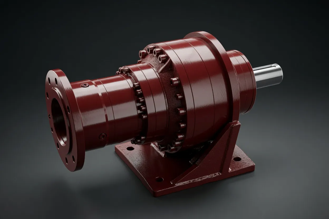
CNC machining centers and lathes achieve their precision through servo-driven feed axes and, in some configurations, geared spindle drives that extend the machine’s torque range at low RPM. Planetary gearboxes in these applications must deliver arc-second positioning accuracy, high torsional stiffness, and zero-maintenance reliability across tens of thousands of operating hours. This guide covers the engineering behind planetary gearbox selection for CNC machine tool spindle and feed drive applications.
Feed Axis Drives in CNC Machines
CNC feed axes (X, Y, Z, and rotary A/B/C axes) convert servo motor rotation into precise linear or angular workpiece-to-tool positioning. A precision planetary gearbox between the servo motor and the ball screw or rack-and-pinion feed mechanism provides the torque multiplication needed to accelerate heavy slides and workpiece tables while maintaining the sub-micron positioning resolution that modern CNC machining demands. Ratios of 3:1 to 20:1 are typical, with the specific value chosen to optimize the motor’s torque-speed operating point against the feed axis’s force and speed requirements.
Feed axis gearboxes must have backlash below 3 arcminutes — and below 1 arcminute for precision grinding and jig boring applications — to ensure that the CNC controller’s interpolated motion commands produce the intended tool path without dead-zone distortion at direction reversals. A low backlash planetary gearbox with preloaded output bearings and ground helical gears achieves this while maintaining the torsional stiffness (above 100 Nm/arcmin) needed for high servo bandwidth and fast settling time at the end of rapid traverse moves.
Geared Spindle Drives
Why Some Spindles Use Planetary Gearboxes
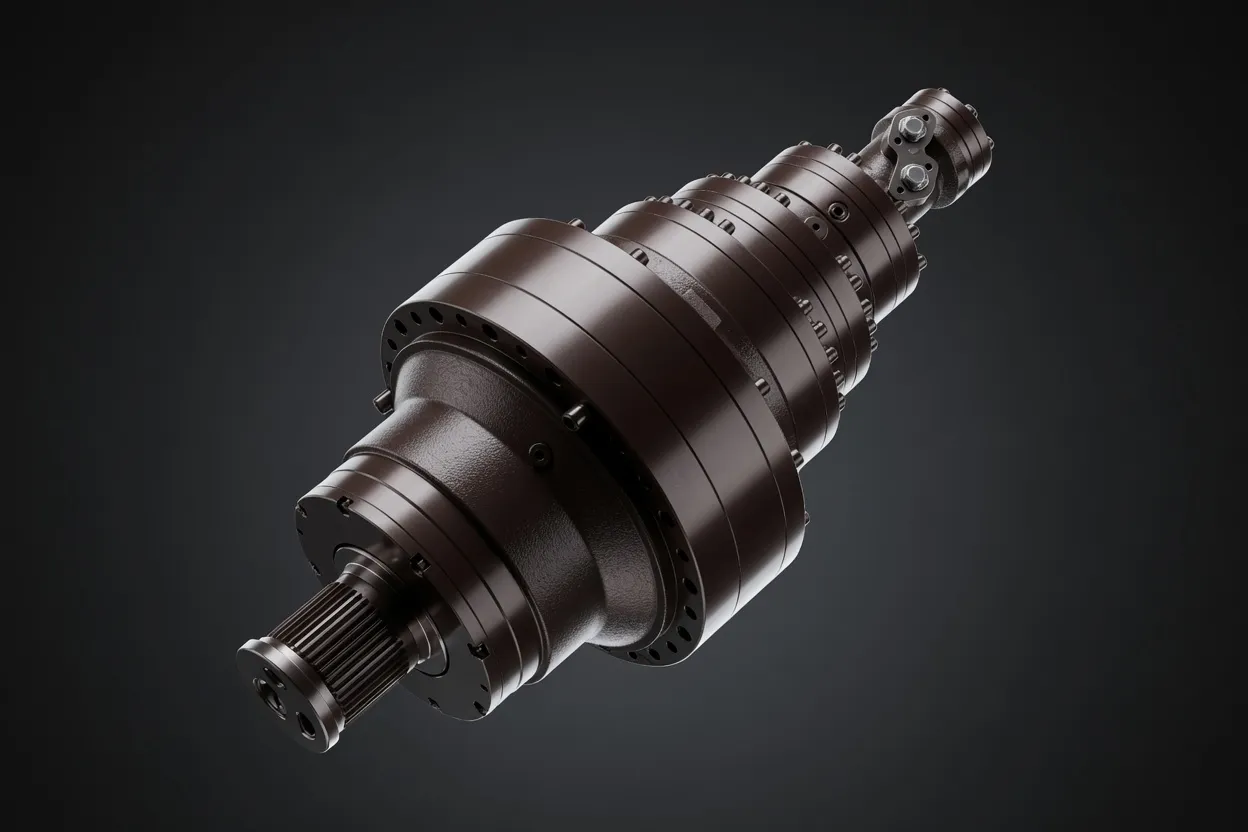
While most modern CNC spindles use direct-drive or belt-drive motor connections, some heavy-duty machining centers incorporate a two-speed planetary gearbox between the spindle motor and the spindle shaft. The gearbox provides a low-range ratio (typically 4:1 to 6:1) for high-torque, low-RPM cutting of tough materials like titanium and Inconel, and a direct-drive (1:1) high-range for high-speed finishing operations in aluminum and mild steel. This arrangement extends the spindle’s useful torque-speed envelope beyond what the motor alone can deliver.
Spindle Gearbox Precision Requirements
Spindle gearboxes must contribute minimal runout and vibration to the spindle system — the rotating accuracy of a high-precision machining center spindle is measured in micrometers. Gear transmission error below 20 arcseconds and dynamic balance quality of G1.0 or better ensure that the gearbox does not degrade the spindle’s inherent accuracy. These specifications demand the highest grade of gear manufacturing: profile and lead errors within 3 μm, pitch deviation within 5 μm, and surface finish below Ra 0.4 μm on all tooth flanks.
Technical Specifications for CNC Gearboxes
Angular Backlash
Feed axes: below 3 arcminutes standard, below 1 arcminute for precision machines. Spindle gearboxes: below 1 arcminute to prevent chatter-inducing dead zones at low-speed heavy cutting where the tool tends to grab and release cyclically.
Torsional Stiffness
100–200 Nm/arcmin for standard machining centers. 300+ Nm/arcmin for large-format machine tools with long feed axes where structural compliance limits servo bandwidth. Higher stiffness enables higher loop gains, reducing settling time and improving contouring accuracy.
⚙️ Efficiency at Low Speed
CNC feed axes spend significant time at low speed during contouring cuts. Gearbox efficiency at 10–50 RPM output determines the motor’s required sizing and the controller’s ability to maintain smooth velocity at these critical machining speeds. Helical planetary gears maintain higher efficiency at low speed than spur designs.
Vibration Level
Vibration from the gearbox propagates through the machine structure to the cutting tool, potentially causing surface finish defects. Specify gearboxes with vibration levels below 0.5 mm/s RMS at the housing to ensure the gearbox’s contribution to tool-tip vibration remains below the threshold of surface-quality impact.
Integration with CNC Control Systems
Encoder Resolution Through Ratio
The effective position resolution at the feed axis equals the motor encoder resolution multiplied by the gear ratio. Verify that this effective resolution meets the CNC controller’s minimum interpolation increment — typically 0.1 μm for modern controllers. A 10:1 ratio with a 24-bit encoder (16.7 million counts/revolution) provides 0.002 μm resolution per count at the output, far exceeding most requirements.
Servo Loop Bandwidth Verification
Run a frequency-response test (chirp or swept-sine) on the assembled axis to verify that the closed-loop bandwidth meets the machine tool builder’s specification — typically 50–100 Hz for feed axes. If bandwidth is insufficient, check for excessive compliance in the gearbox mounting, coupling, or ball-screw support bearings.
Backlash Compensation Configuration
Enter the measured gearbox backlash value into the CNC controller’s backlash compensation parameter. Modern controllers apply predictive compensation based on the direction of travel, pre-positioning the motor before the reversal to minimize the dead-zone effect on the machined surface.
Thermal Growth Management
During sustained machining, gearbox heating expands the housing and shifts the output shaft position. High-precision machines use temperature-compensated positioning: a sensor on the gearbox housing feeds the CNC controller, which adjusts the axis position offset in real time to maintain workpiece accuracy despite thermal drift.
Maintenance for Long-Term Machining Accuracy
CNC machine gearboxes are sealed and lifetime-lubricated under normal operating conditions. The primary maintenance action is periodic backlash verification — annually for production machining centers, semi-annually for precision machines. Measure backlash using the machine’s built-in measurement cycle or an external indicator, and compare to the commissioning baseline. When backlash exceeds the CNC controller’s compensation range, or when contouring accuracy at direction reversals degrades below the workpiece tolerance, schedule gearbox replacement during the next planned maintenance window.
Vibration monitoring supplements backlash checks by detecting developing bearing or gear issues before they manifest as workpiece quality problems. A monthly vibration measurement at the gearbox housing, trended over time, reveals gradual degradation that correlates with approaching end of life. This predictive approach prevents the costly scenario of a mid-production gearbox failure that scraps a partially machined workpiece and requires emergency machine downtime.
Why Choose Ever-Power for CNC Machine Gearboxes
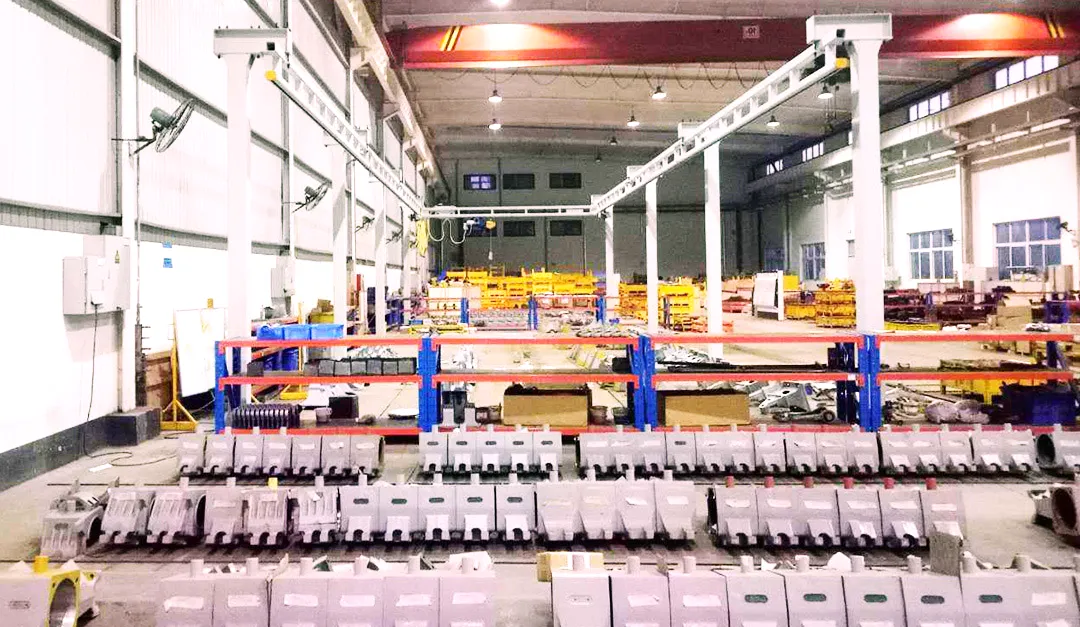
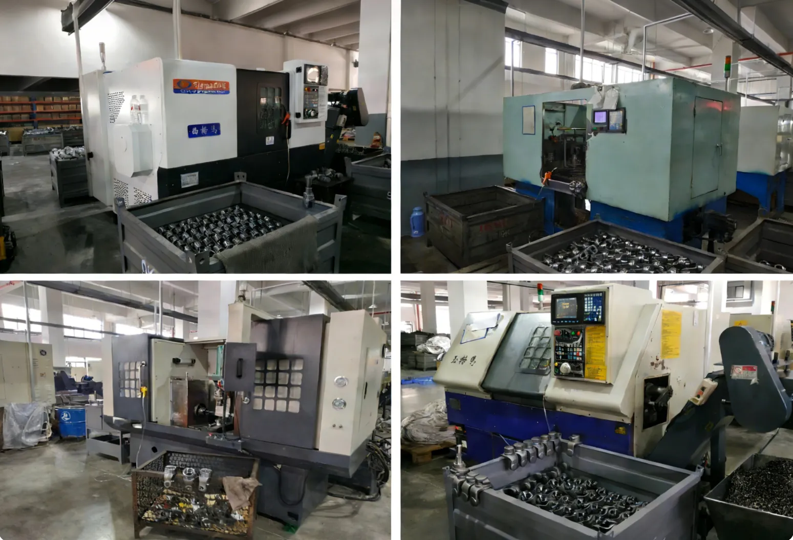
Ultra-Precision Manufacturing
Our CNC gear grinding lines produce tooth profiles with lead and profile errors within 3 μm, enabling assembled gearbox backlash below 1 arcminute and transmission error below 20 arcseconds — specifications that satisfy the most demanding machine tool OEM requirements.
Dynamic Balance Certification
Every spindle-application gearbox is dynamically balanced to G1.0 quality and tested for vibration at rated speed. Balance and vibration reports accompany each unit.
️
Machine Tool OEM Support
Our application engineers work with machine tool designers from concept through production launch, providing co-developed gearbox solutions optimized for each machine’s specific stiffness, speed, and accuracy requirements.
Global Machine Tool Supply
We supply CNC gearboxes to machine tool manufacturers across Asia, Europe, and North America with consistent quality, competitive pricing, and lead times aligned to machine production schedules.
Frequently Asked Questions
Achieve Micron-Level Machining Precision
Share your CNC machine specifications and accuracy requirements — our precision gearbox team will recommend the ideal solution.